

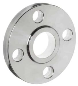
SLIP ON FLANGE
SLIP ON FLANGE
WELD NECK VS SLIP ON FLANGE
Flanged joints made with slip-on flanges are, in the long run, a bit more fragile than connections made with welding neck flanges (in similar service conditions). This seems due to the following facts:
- a welding neck flange features a tapered hub, absent in a socket weld flange, which distributes the mechanical stress between the pipe and the flange more evenly
- a welding neck joint as only one welding area instead of two (socket weld flange).
Another advantage of the welding neck flange is that it can be connected either to pipes and fittings, whereas socket weld flanges suit pipes only.
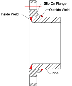
A slip-on flange is connected to the pipe or the fittings by two fillet welds, one executed inside and one outside the cavity of the flange.
The bore size of a slip-on flange is larger than the outside diameter of the connecting pipe, as the pipe has to slide inside the flange to be connected by the execution of a fillet weld.
Slip-On flange has a hole with matching outside diameter of pipe from which pipe can pass. The flange is placed on pipe and fillet welded from both inside and outside. Slip-On Flange is suitable for low pressure and temperature application.
- This type of flange available in large size also
- It can be FF or RF
- The cost of flange and fabrication is moderate.
Slip on flange dimensions are covered in ASME B16.5 – which covers Pipe Flanges and Flanged Fittings for size NPS ½” to 24” for above NPS 26” to 60” it should be as per ASME B16.47.
During a dimensional inspection of slip on flange, you should check for
- Outer & Inner Diameter of body
- Bolt Circle & Bolt Hole Diameter
- Length of the Hub
- Straightness and alignment of the bolt hole
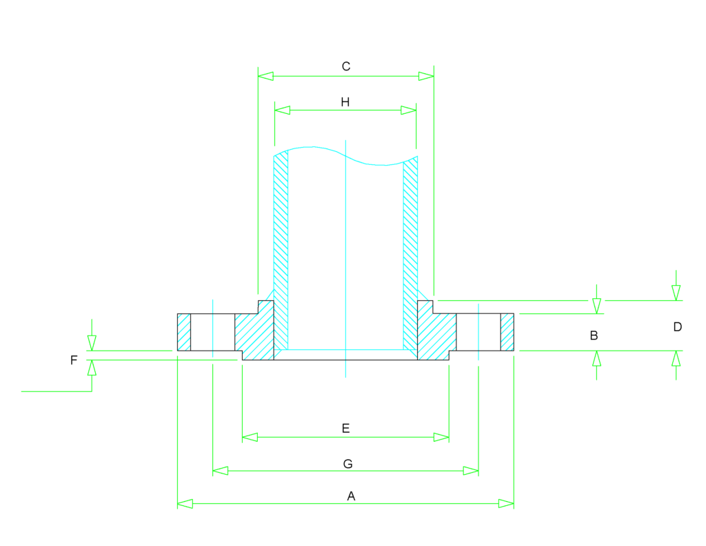
Class 150 Slip-on Flange Dimensions
Size in Inch | Size in mm | Outer Dia. | Flange Thick. | Hub OD | Flange Length | RF Dia. | RF Height | PCD | Socket Bore | No of Bolts | Bolt Size UNC | Machine Bolt Length | RF Stud Length | Hole Size | ISO Stud Size | Weight in kg |
A | B | C | D | E | F | G | H | |||||||||
1/2 | 15 | 90 | 9.6 | 30 | 14 | 34.9 | 2 | 60.3 | 22.2 | 4 | 1/2 | 50 | 55 | 5/8 | M14 | 0.8 |
3/4 | 20 | 100 | 11.2 | 38 | 14 | 42.9 | 2 | 69.9 | 27.7 | 4 | 1/2 | 50 | 65 | 5/8 | M14 | 0.9 |
1 | 25 | 110 | 12.7 | 49 | 16 | 50.8 | 2 | 79.4 | 34.5 | 4 | 1/2 | 55 | 65 | 5/8 | M14 | 0.9 |
1 1/4 | 32 | 115 | 14.3 | 59 | 19 | 63.5 | 2 | 88.9 | 43.2 | 4 | 1/2 | 55 | 70 | 5/8 | M14 | 1.4 |
1 1/2 | 40 | 125 | 15.9 | 65 | 21 | 73 | 2 | 98.4 | 49.5 | 4 | 1/2 | 65 | 70 | 5/8 | M14 | 1.4 |
2 | 50 | 150 | 17.5 | 78 | 24 | 92.1 | 2 | 120.7 | 61.9 | 4 | 5/8 | 70 | 85 | 3/4 | M16 | 2.3 |
2 1/2 | 65 | 180 | 20.7 | 90 | 27 | 104.8 | 2 | 139.7 | 74.6 | 4 | 5/8 | 75 | 90 | 3/4 | M16 | 3.2 |
3 | 80 | 190 | 22.3 | 108 | 29 | 127 | 2 | 152.4 | 90.7 | 4 | 5/8 | 75 | 90 | 3/4 | M16 | 3.7 |
3 1/2 | 90 | 215 | 22.3 | 122 | 30 | 139.7 | 2 | 177.8 | 103.4 | 8 | 5/8 | 75 | 90 | 3/4 | M16 | 5 |
4 | 100 | 230 | 22.3 | 135 | 32 | 157.2 | 2 | 190.5 | 116.1 | 8 | 5/8 | 75 | 90 | 3/4 | M16 | 5.9 |
5 | 125 | 255 | 22.3 | 164 | 35 | 185.7 | 2 | 215.9 | 143.8 | 8 | 3/4 | 85 | 95 | 7/8 | M20 | 6.8 |
6 | 150 | 280 | 23.9 | 192 | 38 | 215.9 | 2 | 241.3 | 170.7 | 8 | 3/4 | 85 | 100 | 7/8 | M20 | 8.6 |
8 | 200 | 345 | 27 | 246 | 43 | 269.9 | 2 | 298.5 | 221.5 | 8 | 3/4 | 90 | 110 | 7/8 | M20 | 13.7 |
10 | 250 | 405 | 28.6 | 305 | 48 | 323.8 | 2 | 362 | 276.2 | 12 | 7/8 | 100 | 115 | 1 | M24 | 19.5 |
12 | 300 | 485 | 30.2 | 365 | 54 | 381 | 2 | 431.8 | 327 | 12 | 7/8 | 100 | 120 | 1 | M24 | 29 |
14 | 350 | 535 | 33.4 | 400 | 56 | 412.8 | 2 | 476.3 | 359.2 | 12 | 1 | 115 | 135 | 1 1/8 | M27 | 41 |
16 | 400 | 595 | 35 | 457 | 62 | 469.9 | 2 | 539.8 | 410.5 | 16 | 1 | 115 | 135 | 1 1/8 | M27 | 54 |
18 | 450 | 635 | 38.1 | 505 | 67 | 533.4 | 2 | 577.9 | 461.8 | 16 | 1 1/8 | 125 | 145 | 1 1/4 | M30 | 59 |
20 | 500 | 700 | 41.3 | 559 | 71 | 584.2 | 2 | 635 | 513.1 | 20 | 1 1/8 | 140 | 160 | 1 1/4 | M30 | 75 |
24 | 600 | 815 | 46.1 | 663 | 81 | 692.2 | 2 | 749.3 | 616 | 20 | 1 1/4 | 150 | 170 | 1 3/8 | M33 | 100 |
Class 300 Slip-on Flange Dimensions
Size in Inch | Size in mm | Outer Dia. | Flange Thick. | Hub OD | Flange Length | RF Dia. | RF Height | PCD | Socket Bore | No of Bolts | Bolt Size UNC | Machine Bolt Length | RF Stud Length | Hole Size | ISO Stud Size | Weight in kg |
A | B | C | D | E | F | G | H | |||||||||
1/2 | 15 | 95 | 12.7 | 38 | 21 | 34.9 | 2 | 66.7 | 22.2 | 4 | 1/2 | 55 | 65 | 5/8 | M14 | 1.2 |
3/4 | 20 | 115 | 14.3 | 48 | 24 | 42.9 | 2 | 82.6 | 27.7 | 4 | 5/8 | 65 | 75 | 3/4 | M16 | 1.4 |
1 | 25 | 125 | 15.9 | 54 | 25 | 50.8 | 2 | 88.9 | 34.5 | 4 | 5/8 | 65 | 75 | 3/4 | M16 | 1.4 |
1 1/4 | 32 | 135 | 17.5 | 64 | 25 | 63.5 | 2 | 98.4 | 43.2 | 4 | 5/8 | 70 | 85 | 3/4 | M16 | 1.8 |
1 1/2 | 40 | 155 | 19.1 | 70 | 29 | 73 | 2 | 114.3 | 49.5 | 4 | 3/4 | 75 | 90 | 7/8 | M20 | 2.7 |
2 | 50 | 165 | 20.7 | 84 | 32 | 92.1 | 2 | 127 | 61.9 | 8 | 5/8 | 75 | 90 | 3/4 | M16 | 3.2 |
2 1/2 | 65 | 190 | 23.9 | 100 | 37 | 104.8 | 2 | 149.2 | 74.6 | 8 | 3/4 | 85 | 100 | 7/8 | M20 | 4.6 |
3 | 80 | 210 | 27 | 117 | 41 | 127 | 2 | 168.3 | 90.7 | 8 | 3/4 | 90 | 110 | 7/8 | M20 | 5.9 |
3 1/2 | 90 | 230 | 28.6 | 133 | 43 | 139.7 | 2 | 184.2 | 103.4 | 8 | 3/4 | 95 | 110 | 7/8 | M20 | 7.7 |
4 | 100 | 255 | 30.2 | 146 | 46 | 157.2 | 2 | 200 | 116.8 | 8 | 3/4 | 95 | 115 | 7/8 | M20 | 10 |
5 | 125 | 280 | 33.4 | 178 | 49 | 185.7 | 2 | 235 | 144.4 | 8 | 3/4 | 110 | 120 | 7/8 | M20 | 12.7 |
6 | 150 | 320 | 35 | 206 | 51 | 215.9 | 2 | 269.9 | 171.4 | 12 | 3/4 | 110 | 120 | 7/8 | M20 | 17.7 |
8 | 200 | 380 | 39.7 | 260 | 60 | 269.9 | 2 | 330.2 | 222.2 | 12 | 7/8 | 120 | 140 | 1 | M24 | 26 |
10 | 250 | 445 | 46.1 | 321 | 65 | 323.8 | 2 | 387.4 | 277.4 | 16 | 1 | 140 | 160 | 1 1/8 | M27 | 36 |
12 | 300 | 520 | 49.3 | 375 | 71 | 381 | 2 | 450.8 | 328.2 | 16 | 1 1/8 | 145 | 170 | 1 1/4 | M30 | 52 |
14 | 350 | 585 | 52.4 | 425 | 75 | 412.8 | 2 | 514.4 | 360.2 | 20 | 1 1/8 | 160 | 180 | 1 1/4 | M30 | 75 |
16 | 400 | 650 | 55.6 | 483 | 81 | 469.9 | 2 | 571.5 | 411.2 | 20 | 1 1/4 | 165 | 190 | 1 3/8 | M33 | 86 |
18 | 450 | 710 | 58.8 | 533 | 87 | 533.4 | 2 | 628.6 | 462.3 | 24 | 1 1/4 | 170 | 195 | 1 3/8 | M33 | 113 |
20 | 500 | 775 | 62 | 587 | 94 | 584.2 | 2 | 685.8 | 514.4 | 24 | 1 1/4 | 185 | 205 | 1 3/8 | M33 | 143 |
24 | 600 | 915 | 68.3 | 702 | 105 | 692.2 | 2 | 812.8 | 616 | 24 | 1 1/2 | 205 | 230 | 1 5/8 | M39 | 216 |
Class 400 Slip-on Flange Dimensions
Size in Inch | Size in mm | Outer Dia. | Flange Thickness | Hub OD | Flange Length | RF Dia. | RF Height | PCD | Socket Bore | No of Bolts | Bolt Size UNC | RF Stud Length | Hole Size | ISO Stud Size | Weight in kg |
A | B | C | D | E | F | G | H | ||||||||
1/2 | 15 | 95 | 14.3 | 38 | 22 | 34.9 | 7 | 66.7 | 22.2 | 4 | 1/2 | 75 | 5/8 | M14 | 1.3 |
3/4 | 20 | 115 | 15.9 | 48 | 25 | 42.9 | 7 | 82.6 | 27.7 | 4 | 5/8 | 90 | 3/4 | M16 | 1.5 |
1 | 25 | 125 | 17.5 | 54 | 27 | 50.8 | 7 | 88.9 | 34.5 | 4 | 5/8 | 90 | 3/4 | M16 | 1.8 |
1 1/4 | 32 | 135 | 20.7 | 64 | 29 | 63.5 | 7 | 98.4 | 43.2 | 4 | 5/8 | 95 | 3/4 | M16 | 2.3 |
1 1/2 | 40 | 155 | 22.3 | 70 | 32 | 73 | 7 | 114.3 | 49.5 | 4 | 3/4 | 110 | 7/8 | M20 | 3.2 |
2 | 50 | 165 | 25.4 | 84 | 37 | 92.1 | 7 | 127 | 61.9 | 8 | 5/8 | 110 | 3/4 | M16 | 4.1 |
2 1/2 | 65 | 190 | 28.6 | 100 | 41 | 104.8 | 7 | 149.2 | 74.6 | 8 | 3/4 | 120 | 7/8 | M20 | 5.9 |
3 | 80 | 210 | 31.8 | 117 | 46 | 127 | 7 | 168.3 | 90.7 | 8 | 3/4 | 125 | 7/8 | M20 | 7.3 |
4 | 100 | 255 | 35 | 146 | 51 | 157.2 | 7 | 200 | 116.1 | 8 | 7/8 | 140 | 1 | M24 | 11.8 |
5 | 125 | 280 | 38.1 | 178 | 54 | 185.7 | 7 | 235 | 143.8 | 8 | 7/8 | 145 | 1 | M24 | 14.1 |
6 | 150 | 320 | 41.3 | 206 | 57 | 215.9 | 7 | 269.9 | 170.7 | 12 | 7/8 | 150 | 1 | M24 | 20 |
8 | 200 | 380 | 47.7 | 260 | 68 | 269.9 | 7 | 330 | 221.5 | 12 | 1 | 170 | 1 1/8 | M27 | 31 |
10 | 250 | 445 | 54 | 321 | 73 | 323.8 | 7 | 387.4 | 276.2 | 16 | 1 1/8 | 190 | 1 1/4 | M30 | 42 |
12 | 300 | 520 | 57.2 | 375 | 79 | 381 | 7 | 450.8 | 327 | 16 | 1 1/4 | 205 | 1 3/8 | M33 | 59 |
14 | 350 | 585 | 60.4 | 425 | 84 | 412.8 | 7 | 514.4 | 359.2 | 20 | 1 1/4 | 210 | 1 3/8 | M33 | 82 |
16 | 400 | 650 | 63.5 | 483 | 94 | 469.9 | 7 | 571.5 | 410.5 | 20 | 1 3/8 | 220 | 1 1/2 | M36 | 107 |
18 | 450 | 710 | 66.7 | 533 | 98 | 533.4 | 7 | 628.6 | 461.8 | 24 | 1 3/8 | 230 | 1 1/2 | M36 | 130 |
20 | 500 | 775 | 69.9 | 587 | 102 | 584.2 | 7 | 685.8 | 513.1 | 24 | 1 1/2 | 240 | 1 3/4 | M39 | 157 |
24 | 600 | 915 | 76.2 | 702 | 114 | 692.2 | 7 | 812.8 | 616 | 24 | 1 3/4 | 265 | 1 7/8 | M45 | 232 |
Class 600 Slip-on Flange Dimensions
Size in Inch | Size in mm | Outer Dia. | Flange Thickness | Hub OD | Flange Length | RF Dia. | RF Height | PCD | Socket Bore | No of Bolts | Bolt Size UNC | RF Stud Length | Hole Size | ISO Stud Size | Weight in kg |
A | B | C | D | E | F | G | H | ||||||||
1/2 | 15 | 95 | 14.3 | 38 | 22 | 34.9 | 7 | 66.7 | 22.2 | 4 | 1/2 | 75 | 5/8 | M14 | 1.3 |
3/4 | 20 | 115 | 15.9 | 48 | 25 | 42.9 | 7 | 82.6 | 27.7 | 4 | 5/8 | 90 | 3/4 | M16 | 1.4 |
1 | 25 | 125 | 17.5 | 54 | 27 | 50.8 | 7 | 88.9 | 34.5 | 4 | 5/8 | 90 | 3/4 | M16 | 1.8 |
1 1/4 | 32 | 135 | 20.7 | 64 | 29 | 63.5 | 7 | 98.4 | 43.2 | 4 | 5/8 | 95 | 3/4 | M16 | 2.3 |
1 1/2 | 40 | 155 | 22.3 | 70 | 32 | 73 | 7 | 114.3 | 49.5 | 4 | 3/4 | 110 | 7/8 | M20 | 3.2 |
2 | 50 | 165 | 25.4 | 84 | 37 | 92.1 | 7 | 127 | 61.9 | 8 | 5/8 | 110 | 3/4 | M16 | 4.1 |
2 1/2 | 65 | 190 | 28.6 | 100 | 41 | 104.8 | 7 | 149.2 | 74.6 | 8 | 3/4 | 120 | 7/8 | M20 | 5.9 |
3 | 80 | 210 | 31.8 | 117 | 46 | 127 | 7 | 168.3 | 90.7 | 8 | 3/4 | 125 | 7/8 | M20 | 7.3 |
4 | 100 | 275 | 38.1 | 152 | 54 | 157.2 | 7 | 215.9 | 116.1 | 8 | 7/8 | 145 | 1 | M24 | 16.8 |
5 | 125 | 330 | 44.5 | 189 | 60 | 185.7 | 7 | 266.7 | 143.8 | 8 | 1 | 165 | 1 1/8 | M27 | 29 |
6 | 150 | 355 | 47.7 | 222 | 67 | 215.9 | 7 | 292.1 | 170.7 | 12 | 1 | 170 | 1 1/8 | M27 | 36 |
8 | 200 | 420 | 55.6 | 273 | 76 | 269.9 | 7 | 349.2 | 221.5 | 12 | 1 1/8 | 190 | 1 1/4 | M30 | 52 |
10 | 250 | 510 | 63.5 | 343 | 86 | 323.8 | 7 | 431.8 | 276.2 | 16 | 1 1/4 | 215 | 1 3/8 | M33 | 77 |
12 | 300 | 560 | 66.7 | 400 | 92 | 381 | 7 | 489 | 327 | 20 | 1 1/4 | 220 | 1 3/8 | M33 | 91 |
14 | 350 | 605 | 69.9 | 432 | 94 | 412.8 | 7 | 527 | 359.2 | 20 | 1 3/8 | 235 | 1 1/2 | M36 | 105 |
16 | 400 | 685 | 76.2 | 495 | 106 | 469.9 | 7 | 603.2 | 410.5 | 20 | 1 1/2 | 255 | 1 5/8 | M39 | 150 |
18 | 450 | 745 | 82.6 | 546 | 117 | 533.4 | 7 | 654 | 461.8 | 20 | 1 5/8 | 275 | 1 3/4 | M42 | 182 |
20 | 500 | 815 | 88.9 | 610 | 127 | 584.2 | 7 | 723.9 | 513.1 | 24 | 1 5/8 | 285 | 1 3/4 | M42 | 232 |
24 | 600 | 940 | 101.6 | 718 | 140 | 692.2 | 7 | 838.2 | 616 | 24 | 1 7/8 | 330 | 2 | M48 | 332 |
Class 900 Slip-on Flange Dimensions
Size in Inch | Size in mm | Outer Dia. | Flange Thickness | Hub OD | Flange Length | RF Dia. | RF Height | PCD | Socket Bore | No of Bolts | Bolt Size UNC | RF Stud Length | Hole Size | ISO Stud Size | Weight in kg |
A | B | C | D | E | F | G | H | ||||||||
1/2 | 15 | 120 | 22.3 | 38 | 32 | 34.9 | 7 | 82.6 | 22.2 | 4 | 3/4 | 110 | 7/8 | M20 | 1.8 |
3/4 | 20 | 130 | 25.4 | 44 | 35 | 42.9 | 7 | 88.9 | 27.7 | 4 | 3/4 | 115 | 7/8 | M20 | 2.3 |
1 | 25 | 150 | 28.6 | 52 | 41 | 50.8 | 7 | 101.6 | 34.5 | 4 | 7/8 | 125 | 1 | M24 | 3.6 |
1 1/4 | 32 | 160 | 28.6 | 64 | 41 | 63.5 | 7 | 111.1 | 43.2 | 4 | 7/8 | 125 | 1 | M24 | 4.1 |
1 1/2 | 40 | 180 | 31.8 | 70 | 44 | 73 | 7 | 123.8 | 49.5 | 4 | 1 | 140 | 1 1/8 | M27 | 5.5 |
2 | 50 | 215 | 38.1 | 105 | 57 | 92.1 | 7 | 165.1 | 61.9 | 8 | 7/8 | 145 | 1 | M24 | 11.5 |
2 1/2 | 65 | 245 | 41.3 | 124 | 64 | 104.8 | 7 | 190.5 | 74.6 | 8 | 1 | 160 | 1 1/8 | M27 | 16.5 |
3 | 80 | 240 | 38.1 | 127 | 54 | 127 | 7 | 190.5 | 90.7 | 8 | 7/8 | 145 | 1 | M24 | 12 |
4 | 100 | 290 | 44.5 | 159 | 70 | 157.2 | 7 | 235 | 116.1 | 8 | 1 1/8 | 170 | 1 1/4 | M30 | 24 |
5 | 125 | 350 | 50.8 | 190 | 79 | 185.7 | 7 | 279.4 | 143.8 | 8 | 1 1/4 | 190 | 1 3/8 | M33 | 38 |
6 | 150 | 380 | 55.6 | 235 | 86 | 215.9 | 7 | 317.5 | 170.7 | 12 | 1 1/8 | 190 | 1 1/4 | M30 | 50 |
8 | 200 | 470 | 63.5 | 298 | 102 | 269.9 | 7 | 393.7 | 221.5 | 12 | 1 3/8 | 220 | 1 1/2 | M36 | 78 |
10 | 250 | 545 | 69.9 | 368 | 108 | 323.8 | 7 | 469.9 | 276.2 | 16 | 1 3/8 | 235 | 1 1/2 | M36 | 112 |
12 | 300 | 610 | 79.4 | 419 | 117 | 381 | 7 | 533.4 | 327 | 20 | 1 3/8 | 255 | 1 1/2 | M36 | 148 |
14 | 350 | 640 | 85.8 | 451 | 130 | 412.8 | 7 | 558.8 | 359.2 | 20 | 1 1/2 | 275 | 1 5/8 | M39 | 182 |
16 | 400 | 705 | 88.9 | 508 | 133 | 469.9 | 7 | 616 | 410.5 | 20 | 1 5/8 | 285 | 1 3/4 | M42 | 193 |
18 | 450 | 785 | 101.6 | 565 | 152 | 533.4 | 7 | 685.8 | 461.8 | 20 | 1 7/8 | 325 | 2 | M48 | 258 |
20 | 500 | 855 | 108 | 622 | 159 | 584.2 | 7 | 749.3 | 513.1 | 20 | 2 | 350 | 2 1/8 | M52 | 317 |
24 | 600 | 1040 | 139.7 | 749 | 203 | 692.2 | 7 | 901.7 | 616 | 20 | 2 1/2 | 440 | 2 5/8 | M64 | 608 |
Class 1500 Slip-on Flange Dimensions
Size in Inch | Size in mm | Outer Dia. | Flange Thickness | Hub OD | Flange Length | RF Dia. | RF Height | PCD | Socket Bore | No of Bolts | Bolt Size UNC | RF Stud Length | Hole Size | ISO Stud Size | Weight in kg |
A | B | C | D | E | F | G | H | ||||||||
1/2 | 15 | 120 | 22.3 | 38 | 32 | 34.9 | 7 | 82.6 | 22.2 | 4 | 3/4 | 110 | 7/8 | M20 | 1.8 |
3/4 | 20 | 130 | 25.4 | 44 | 35 | 42.9 | 7 | 88.9 | 27.7 | 4 | 3/4 | 115 | 7/8 | M20 | 2.3 |
1 | 25 | 150 | 28.6 | 52 | 41 | 50.8 | 7 | 101.6 | 34.5 | 4 | 7/8 | 125 | 1 | M24 | 3.7 |
1 1/4 | 32 | 160 | 28.6 | 64 | 41 | 63.5 | 7 | 111.1 | 43.2 | 4 | 7/8 | 125 | 1 | M24 | 4.1 |
1 1/2 | 40 | 180 | 31.8 | 70 | 44 | 73 | 7 | 123.8 | 49.5 | 4 | 1 | 140 | 1 1/8 | M27 | 5.5 |
2 | 50 | 215 | 38.1 | 105 | 57 | 92.1 | 7 | 165.1 | 61.9 | 8 | 7/8 | 145 | 1 | M24 | 9.8 |
2 1/2 | 65 | 245 | 41.3 | 124 | 64 | 104.8 | 7 | 190.5 | 74.6 | 8 | 1 | 160 | 1 1/8 | M27 | 16.4 |